|
(0)--fm.thing.net--(0)
|
(0)
How to build a 1W transmitter Tetsuo style
Step eight : 3 tricky bits
Estimated time for step eight : 20 - 25 minutes
You will need the following:
Solder Iron
Solder
Copper Board
Components (1 8.5 Turns Molded Coil,Japanese ISV126, IT33 or US Motorola MV209 Vari-cap,2SC1907 Transistor)
Tweezers
These 3 componnets actually finish the transmitter part of the circuit, the rest is for amplifying the signal. You can actually run the transmitter when you have added these three components and its a good idea to do so to test it. So first follow these steps:
A) With the Japanese ISV126, IT33 or US Motorola MV209 Vari-cap (also just called a 'vari-cap'), look at the component and you will see that one end has a thick dark line. This end of the vari-cap needs to be soldered to Square C.
B) then solder the other end to the copper board....not so tricky really.
C) then get the coil (coil A in tetsuos diagram) and solder one end to Square D, and the other to the copper board. Also not so tricky really.
D) this last component is a bit more difficult. Get the 2SC1907 Transistor and have a good look at it. What you should see is that it has a black plastic body with three legs. Its very important that you solder the right legs to the right squares on the board. So....one side of the body of the transistor should be flat. Make sure the flat side points in the same direction as the flat side in Tetsuos diagram[x]. So you want to ahve the flat side facing 'up'.

E) Then solder the left leg to Square A.
F) Solder the middle leg to Square X.
G) Solder the right leg to Square F.
You should now have completed these parts of the diagram:

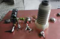
And it should look something like this:

Then proceed to STEP NINE.