|
(0)--fm.thing.net--(0)
|
(0)
How to build a 1W transmitter Tetsuo style
Step nine : do the rest...
Estimated time for step eight : 30 - 45 minutes
You will need the following:
Solder Iron
Solder
Copper Board
The rest of the Components
Tweezers
Ok, so now you have the hang of things. There is nothing new you need to know to finish this circuit. the only tricky bit is to make sure that the 2SC2538 or 2053 Transistor and the 2SC1970 Transistor are soldered the right way round. With the 2SC2538 the flat side will face 'down'. With the 2SC1970 you will see it has a silver side. This should face 'up'. So do the rest:
51K === (green-brown-black) (resistor)
solder one end to Square X, one end to Square Y.
10PF Ceramic (capacitor)
Solder one end to Square F, one end to Square G
1K === (brown-black-red) (resisitor)
Solder one end to Square G, one end to the copper board.
Solder 2SC2538 (see above)
3.5-4.5 Turns Molded Coil (5mm diameter bobbin)(inductance=ca.0.3MH)
Solder one end to Square Y, one end to Square H
0.01MF (103) Ceramic (capacitor)
One end to Square Y, one end to copper board
0.01MF (103) Ceramic (capacitor)
one end to Square Z, one end to copper board
10PF Ceramic (capacitor)
one end to Square H, the other to squrae I
300K === (orange-black-brown) (resistor)
One end to Square I, one end to copper board
Solder 2SC1970 (see above)
1MH Fixed RFC
One end to Square J, one end to Square Z
10PF Ceramic (capacitor)
One end to Square J, one end to square K
33PF Ceramic (capacitor)
One end to Square K, one end to copper board
3.5-4.5 Turns Molded Coil (5mm diameter bobbin)(inductance=ca.0.3MH)
one end to Square K, one end to Square L
33PF Ceramic (capacitor)
one end to Square L, one end to the copper board
And THATS IT!!!!!!!!!!!!!!!!!!!!!!!!
Next, when we get a few minutes, we will tell you how to connect teh antenna and the power. You can try this yourself already...You'll be able to get it going by looking at Tetsuos diagrams, just remember the power in is DC not AC...try it but watch this spot as their will be this documentation online soon....heres some photos of us for interest...

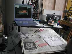
our workshop ready to get the stream from Tetsuo

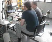
Adam and Jan doing workshop with Tetsuo

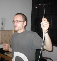
radio liberty (Jan with antenna)

our ex-.com UPS power supply for the transmitter

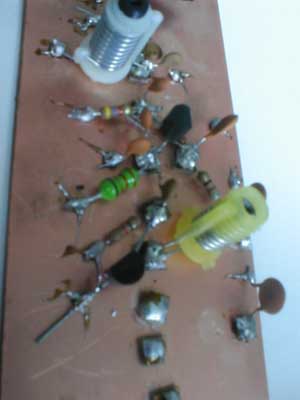
partially completed transmitter