|
(0)--fm.thing.net--(0)
|
(0)
How to build a 1W transmitter Tetsuo style
Step seven : more soldering
Estimated time for step sseven : 15-20 minutes
You will need the following:
Solder Iron
Solder
Copper Board
Components
Tweezers
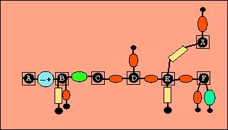
Solder the following components:
100PF (101) Ceramic (capacitor)
one end to Square B, one end to copper board.
4.7MH Fixed RFC (inductor)
one end to Square B, one end to Square C.
10PF Ceramic (capacitor)
one end to Square C, one end to Square D.
10PF Ceramic (capacitor)
one end to Square D, one end to copper board.
33PF Ceramic (capacitor)
one end to Square D, one end to Square E.
4.7K === (yellow-violet-red) (resistor)
One end to square E, one end to the copper board.
22K === (red-red-orange) (resistor)
One end to square E, one end to Square X.
33PF Ceramic (capacitor)
one end to Square E, one end to Square F.
33PF Ceramic (capacitor)
one end to Square F, one end to the copper board.
2.2MH Fixed RFC (inductor)
one end to square F, one end to copper board.
0.01MF (103) Ceramic (capacitor) one end to square X, one end to copper board.
You should now have completed these parts of the diagram:

Don't worry though if your soldering looks messy.
Then proceed to STEP EIGHT.