(0)
|
(0)--fm.thing.net--(0)
|
(0)
How to build a 1W transmitter Tetsuo style
Ok, we are assuming that you ahve no experience with electronics and we will attempt to explain this in as simple terms as posisble as we learnt it from Tetsuo. First of course, we must say a BIG thank you to Tetsuo Kogawa, his generosity and kindness has been a wonderful gift to us and our project. Many many thanks to you Tetsuo [x].
Step one : Get the bits and pieces
Before you do anything you need to source the tools and components. We will start first with the very basics - tools.
You will need the following:
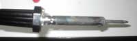
Solder Iron [x]
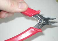
The solder iron can be purchased at any electronics or hardware store. In the US (NYC) they were about $15 US dollars. Make sure you buy one with a very thing 'pointy' end for soldering accurately, and it should be about 15-20 Watts. You will also need some solder which is the wire that you use the soldering iron to melt to join the components to the circuit board.Wire Cutters [x]
These should be a really sharp pair of wire cutters, preferably with a very fine end for cutting wire close to components or solder points. These were about $6.
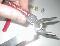
Pliers [x]
A good pair of general purpose pliers is always useful, we used them also instead of tweezers for holding components while we soldered them but we don't recommend this as the pliers are not really for precision uses like this.
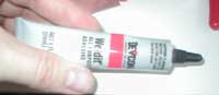
Glue [x]
Get some really good glue that will dry in about 5 minutes. The type of glue that you have to mix is not recommended as it takes too long to mix and dry. Our glue was flamable but while the glue was certainly heated at times by the solder iron it was never exposed to an open flame and hence we had no difficulties with this, be a bit careful though and if you are not sure then do some cautious tests first.
In addition we suggest you get a hold of some 'tweezers', the type with a really long 'nose'. This is so you can hold some of the components while you solder them as the components are small and difficult to hold by hand and the components can become too hot to hold while you solder them.
Lastly you need a good strong cutting knife and a steel ruler.
Ok...now the components. We were lucky enough to have all the requisite parts sent to us by Tetsuo from Japan, however its is possible to get them all from a good electronics store.
The parts are:
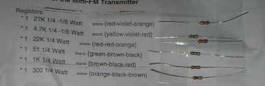
Resistors [x]
These are the long cylindrical components with coloured markings. If you dont know what one is then go to the electronics store and just say you want some then you'll see ;-) ... The most important thing to know is that it doesn't matter which way round you solder these components, there is no 'back' or 'front' ('polarity'). Go to an electronics store and get the following:
1 27K 1/4 -1/8 Watt === (red-violet-orange)
1 4.7K 1/4 -1/8 Watt === (yellow-violet-red)
1 22K 1/4 Watt === (red-red-orange)
1 51 1/4 Watt === (green-brown-black)
1 1K 1/4 Watt === (brown-black-red)
1 300 1/4 Watt === (orange-black-brown)
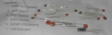
Capacitors[x]
There are many types of capacitors. You need to worry about only 2 types - 'ceramic' (usually these are circular and flat, and brown coloured but don't be surprised if the ones you get look slightly different to this) and 'Electrolytic' (these are usually very round cylinders with a shiny plastic coating). The ceramic capacitors can be soldered anyway round but be careful with the electrolytic capacitors as these have a specific direction. Essentially the electrical current needs to flow a particular way through the electrolytic capacitors else they may be destroyed. If you look at the plastic coating you should see a symbol that looks like a minus sign ('-'), this end needs to be soldered where you see the minus sign on the diagrams but we shall get to that later. Generally the capacitors are marked with their PF ratings or with codes like '101', '102' etc. There is a science to this of course but because we don't know it we recommend that you mark these items clearly when you buy them at the electronics store so you can identify them later, keep each type in seperate bags if necessary. The capacitors you need are:
1 100PF (101) Ceramic
4 10PF Ceramic
5 33PF Ceramic
1 3-4PF Ceramic
3 0.01MF (103) Ceramic
1 1-4.7 MF Electrolytic
We actually didnt have enough 10PF capacitors so we substituted one for an 8PF and it worked fine. As we are not electronics technicians we don't know the rules about this so we just experimented and as we didn't end up wrecking anything then we recommend you should experiment if you have too.
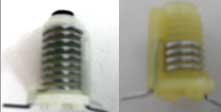
Coils[x]
These are maybe the trickiest things to find. If your electronics shop doesnt have them then we recommend you try and buy them online, at this stage we don't know a good place to get them on the net but give us some time and we will find them. If you know of where these kind of coils can be easily brought then please let us know. It is possible to build these coils by winding coated wire around a pencil if you really get stuck, however we haven't tried this. It also doesnt matter which way you solder these. The coils you need are:
1 8.5 Turns Molded Coil (5mm diameter bobbin)(inductance=ca.0.6-0.7MH)
2 3.5-4.5 Turns Molded Coil (5mm diameter bobbin)(inductance=ca.0.3MH)
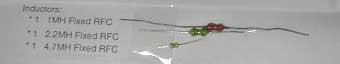
Inductors[x]
These look a bit like resistors with strange bumps in them (from eating too much junk food). It doesnt matter which way you solder these either. You need the following:
1 1MH Fixed RFC
1 2.2MH Fixed RFC
1 4.7MH Fixed RFC
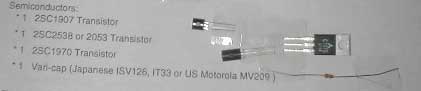
Semiconductors[x]
These are extremely delicate items. Be careful with them and make sure you attach them the right way - we will get to this later. Buy 2 of each of these if you aren't feeling confident about soldering :
1 2SC1907 Transistor
1 2SC2538 or 2053 Transistor
1 2SC1970 Transistor
1 Japanese ISV126, IT33 or US Motorola MV209 Vari-cap
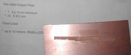
Two sided Copper Plate[x]
This bit is really the genius bit of Tetsuos design. Instead of needing a printed circuit board he uses a design that requires only a copper board. More on this later, however you can buy these types of copper boards from most electronic shops. They are usually doublle sided or single sided copper with an insulating matreial in the middle. We brought one for $4 US dollars. The dimensions you need are:
5 x 10 cm minimum (one large circuit board)
15 5 X 5 mm (15 small squares, you will cut this from the main board above)
Coax Cable
You need this for the antenna, its very common cable and if your electronics shop doesn't have it then go somewhere else as its likely they will be going out of business soon. The recommended diameter type is:
RG62-u [5D2V]
Before we start we recommend you read this :
How to Solder
http://www.irational.org/sic/radio/solder.html
Then proceed to STEP TWO.